
Hoist appliction
1, Features of traditonal system
(1) The traditional system works at heavy load for long time, forward and reverse run frequently, the lifetime of the system is short;
(2) High failure ratio.
(3) Low efficiency, the power factor is less than 0.8.
(4) The safety performance is bad.
.
2, Requests for frequency inverters (VFD)
(1) Big output torque at low frequency, it should run smoothly during working.
(2) Big overload capacity.
(3) Less failure ratio, run stably.
(4) Braking unit and braking resistor should be added.
3, Real application (Tower crane)
3.1 system introduction
The hoist motor in the system is 55kW/380V, the load type is constant torque, to consider its heavy duty characteristic,the frequency inverter should be selected two sizes higher as below:
Model | Power | Voltage | Output Current | Quantity |
FC155-4T-90G | 90KW | 380V | 176A | 1 |
3.2 system diagram
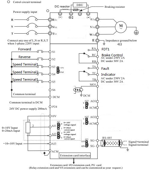
3.3 control logic
(1) The tower crane control system provide the forward and reverse signals, while S1 and COM closed, the tower crane runs forwardly, and while S2 and COM closed, the tower crane runs reversely:
(2) The running speed of crane is controlled by ON/OFF conditions ofS3, S4 and S5, details as below:
S5 | S4 | S3 | Speed |
OFF | OFF | OFF | Speed 0 (F12.02) |
OFF | OFF | ON | Speed 1 (F12.03) |
OFF | ON | OFF | Speed 2 (F12.04) |
OFF | ON | ON | Speed 3 (F12.05) |
ON | OFF | OFF | Speed 4 (F12.06) |
ON | OFF | ON | Speed 5 (F12.07) |
(3) The inverter output a fault signal to the crane control system, while fault happen, the system will brake and stopimmediately.
(4) There is an output FDT1 (controlled by F09.20 and F09.21) ON/OFF signal, while the inverter runs to the settingfrequency, this signal will control the brake to open, to avoid the reverse run happen.
3.4 autotuning
For this kind of heavy duty system, it is better to use Sensorless Vector Control (SVC) mode, it will get better outputtorque performance.
Before using SVC mode, please perform motor autotunning, do it as below steps:
1) Set F00.01=0 (keypad), set correct value of F02.01 ~ F02.04 (based on motor nameplate);
2) If the load can be removed from motor, please set F02.37=2 (Rotation autotuning, get better performance), if the
load cannot be removed from motor, please set F02.37=1 (Static autotuning). The keypad will display “TUNE”.
3) Press the RUN button, wait until the autotuning finish automatically.
4) Change the value of F00.00=0 (Sensorless vector control)
3.5 Parameters setting
No. | Function codes | Default | Setting value | Explanation |
1 | F00.00 | 2 | 0 | Sensorless Vector Control |
2 | F00.01 | 0 | 1 | External singal start / stop |
3 | F00.06 | 0 | 6 | Multi-step speed |
4 | F00.12 | Model depend | 5s | Acceleration time (adjustable) |
5 | F00.13 | Model depend | 0.5s | Deceleration time (adjustable) |
6 | F03.10 | 150% | 200% | Torque uppee limit |
7 | F06.00 | 1 | 1 | Forward |
8 | F06.01 | 2 | 2 | Reverse |
9 | F06.02 | 4 | 12 | Multi-step speed termnial 1 |
10 | F06.03 | 6 | 13 | Multi-step speed termnial 2 |
11 | F06.04 | 12 | 14 | Multi-step speed termnial 3 |
12 | F07.02 | 3 | 3 | Fault output |
13 | F07.03 | 0 | 2 | FDT1 output |
14 | F09.20 | 50.00Hz | 3.00Hz | Setting FDT1 output frequency |
15 | F12.02 | 0.0% | 16% | Multi-step speed 0 (adjustable) |
16 | F12.03 | 0.0% | 16% | Multi-step speed 1 (adjustable) |
17 | F12.04 | 0.0% | 30% | Multi-step speed 2 (adjustable) |
18 | F12.05 | 0.0% | 50% | Multi-step speed 3 (adjustable) |
19 | F12.06 | 0.0% | 70% | Multi-step speed 4 (adjustable) |
20 | F12.07 | 0.0% | 82% | Multi-step speed 5 (adjustable) |
3.6 Problems faced during commissioning
(1) Cause the tower working distance is too long, during down running, the inverter works at regenerated status forlong time, so the braking resistor should be selected bigger, to get better performance. In this system, it isselect as 4ohm, 10kW.